
Lubricating The Rear Suspension And Valve Adjustment
Originally posted to El Cantar de la Lluvia on Tuesday, November 14, 2006
I broke my previous record of time spent working on the bike. The longest session was the valve adjustment. This time I spent three days working on the bike, including an intermission to ride around a bit (yes, I took it to pieces twice).
So, for your pleasure, for your enjoyment, tonight we bring to you:
Note: Do not attempt what is described here without having read the post-96 XR 250 R's shop manual. Use it. If you find that this article is short on technical details, it's because a bunch of japanese already sat down and wrote all those technical details in the shop manual.
Without further ado, let us begin.
Oil and Filter Change
I went from a 15W50 Motul semi-synth oil to a full synth 20W50. This time I left it in for 4000 km, more than I usually do. With the full synth, I expect to be able to leave it longer.
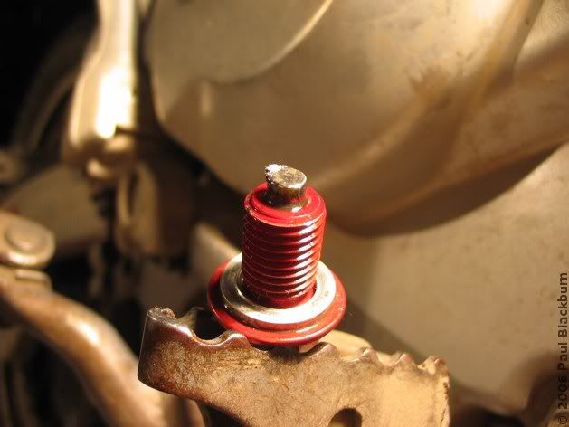
Last oil change, I installed two magnetic oil drain plugs, which I bough at XRsOnly.com. They don't have a reputation of getting your order right, but in my case there was no problem at all. They have a small, strong magnet embedded in the tip, and the idea is that they'll pick up any metallic particles floating around in the oil. Both had a small ball of oily fuzz:
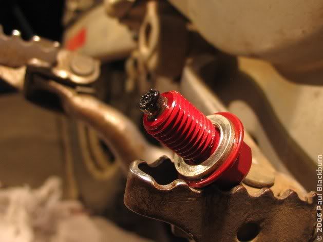
It was hard to remove using a finger, so I had to use paper towel. When spread on a finger, it looks like glossy graphite lipstick, if there were such a thing. Passing the magnet over my painted finger created a very strange pulling sensation.
This is part of the residue, after wiping the tip with a finger.
Lubrication of the Rear Suspension Assembly
Everything in the following diagram was, at one point or another, in my hands as separate pieces. :-)
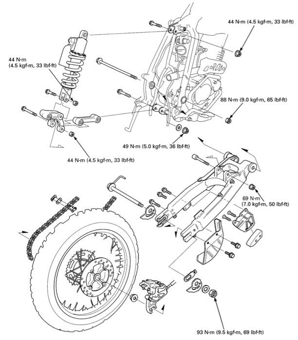
Why did I decide to carry out this maintenance? Because XRs have a tendency to suffer from a stuck swingarm bolt: it corrodes, and since it passes through the engine block, it is subjected to heat, water, dirt and so on. Eventually, when the time comes to take the swingarm bolt out, many find it stuck, and that it takes a ridiculous amount of bashing, WD40, heat, cold and swearing to get it out. To avoid this, and see what state things were in, I decided to take the whole thing apart.

I had no alternative. I rode the bicycle to the mall and bought a 2 x 250 W light stand.

And there was light again!
Below, another spherical bearing, this time from the shock arm. Also completely dry.
And here's the only damaged piece. It's the left needle bearing's collar. It had enough grease, though it was orange in colour, almost rust-orange. Also, the collar was worn.
That night, I left everything lubed up, and the next morning, put it all back together.

Swapping the Renthal Sprocket for a Generic One
Renthal sprockets may be great in a competition, but aluminium is just too soft for dual-sport use. I wanted to find a 45-tooth steel rear sprocket, and after much searching, was lucky enough to find that the XR 400 uses the same anchor bolts as my bike.
Adjusting the Chain Sag
Yawn.
Changing the Clutch Cable
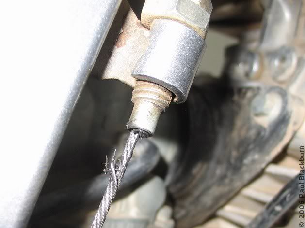
This took me by surprise. I improperly mounted the sheepskin's fastening strap under the clutch cable, instead of over it. This pulled it out of alignment, and made the curved guide tube rub against the cable.
Second Valve Adjustment
I recommend you read the first post about this procedure, if you got here searching for info on adjusting the valves on a 1996 XR 250 R.
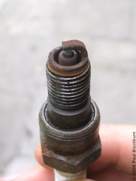
First, wash and clean the area around the spark plug, so crud doesn't fall into the engine when we remove it.
I measured the electrode gap, and it was 0.85 mm, right between the 0.8 and 0.9 mm that the service manual states as min and max.
Next, we remove the seat and gas tank, and clean the area underneath.
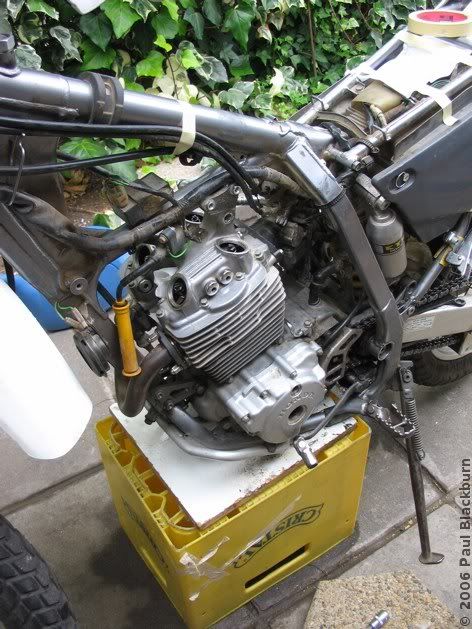
Here's the bike, ready for a valve adjustment: seat and gas tank off, crankshaft and valve timing covers off.
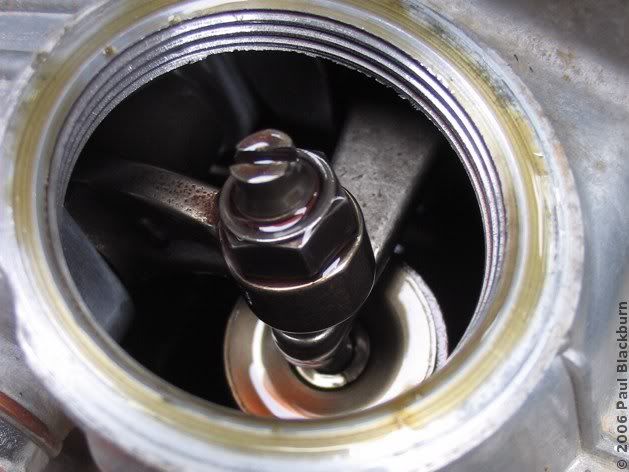
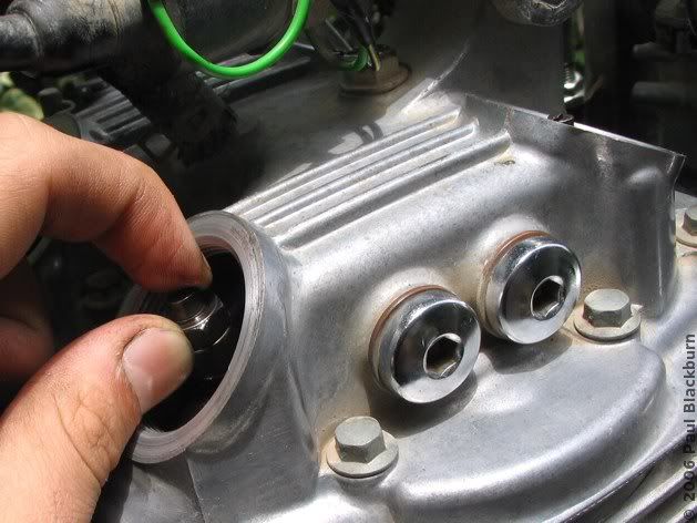
You can see the adjustment screw, with a slotted head, and the adjustment screw lock nut. These two are attached to a rocker arm.
Rotate the crankshaft until the engine is at Top Dead Center. This will happen when you can see a T through the timing hole. Make sure the piston is on a compression stroke. If it is, the valve rocker arms will have enough play in them (both) to make a slight clicking sound when you wiggle them up and down. If they do not wiggle, you are not on the compression stroke.
It is also important to turn the engine anticlockwise in order to line up the T mark.
Some tips:
Once the feelers are bent, measuring the correct separation is easy.

At 20641 km, this is the state of the valves, before adjustment.
The green boxes are the separations specified by the manual.
Regulating the Manual Decompressor System
In the first article on valve adjustments I showed how the manual decompressor works. You must make sure that the manual decompressor does not activate when the front wheel is turned full left or right. Before you cover up the front right hand valve cover, check everything is in order.
Conclusion
The truth is I am in no hurry to do this again. After having finished, I wanted to go for a ride, so I went over to Cuesta Lo Prado, where I found this Chilean Fox.
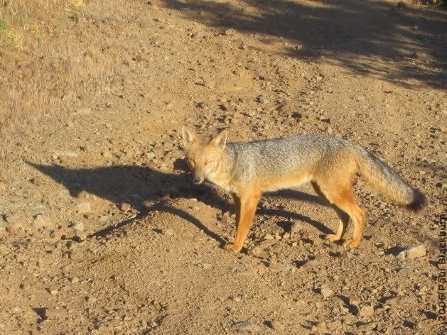
And what of the bike? Same as always. I didn't expect any changes, and there were none that I could feel. These were just things that had to be done.
I broke my previous record of time spent working on the bike. The longest session was the valve adjustment. This time I spent three days working on the bike, including an intermission to ride around a bit (yes, I took it to pieces twice).
So, for your pleasure, for your enjoyment, tonight we bring to you:
- Oil and filter change
- Lubrication of the rear suspension assembly
- Change of rear sprocket (aluminium Renthal) for a generic steel one
- Chain adjustment
- Change of clutch cable
- Second valve adjustment
- Regulation of manual decompression system
Note: Do not attempt what is described here without having read the post-96 XR 250 R's shop manual. Use it. If you find that this article is short on technical details, it's because a bunch of japanese already sat down and wrote all those technical details in the shop manual.
Without further ado, let us begin.
Oil and Filter Change
I went from a 15W50 Motul semi-synth oil to a full synth 20W50. This time I left it in for 4000 km, more than I usually do. With the full synth, I expect to be able to leave it longer.
Last oil change, I installed two magnetic oil drain plugs, which I bough at XRsOnly.com. They don't have a reputation of getting your order right, but in my case there was no problem at all. They have a small, strong magnet embedded in the tip, and the idea is that they'll pick up any metallic particles floating around in the oil. Both had a small ball of oily fuzz:
It was hard to remove using a finger, so I had to use paper towel. When spread on a finger, it looks like glossy graphite lipstick, if there were such a thing. Passing the magnet over my painted finger created a very strange pulling sensation.
This is part of the residue, after wiping the tip with a finger.
Lubrication of the Rear Suspension Assembly
Everything in the following diagram was, at one point or another, in my hands as separate pieces. :-)
Why did I decide to carry out this maintenance? Because XRs have a tendency to suffer from a stuck swingarm bolt: it corrodes, and since it passes through the engine block, it is subjected to heat, water, dirt and so on. Eventually, when the time comes to take the swingarm bolt out, many find it stuck, and that it takes a ridiculous amount of bashing, WD40, heat, cold and swearing to get it out. To avoid this, and see what state things were in, I decided to take the whole thing apart.
The first task was to remove the chain. I bought the bike with the original 1996 chain still on it, and it was in a terrible state: half the o-rings were missing, and the other half were crumbling off. I bought a non-oring chain as a replacement, since I wouldn't be changing the rear sprocket (which was also still stock). That chain was a disaster: perhaps it would have been adequate for an enduro-style day ride, but I was putting it through dust, water, sometimes even snow, and then doing 50 to 100 km of highway riding to get back home. It just couldn't handle it: it stretched one or two adjuster notches every ride.
So eventually I invested in an o-ring chain, and it's still going strong. The only problem is that the master link side plate is very hard to get off. I used a chain breaker tool to push the pins out bit by bit.
Once I had the chain off, I started taking everything apart. It got dark. I was working by the light of two 60 W desk lamps, the type that clip on to things. I dropped one, the filament short-circuited, and the house's fuses blew. I switched them back on, came back to continue working, and 40 seconds later, dropped the other lamp, which shattered. I was standing barefoot, in complete darkness, surrounded by shards of glass. Not nice.
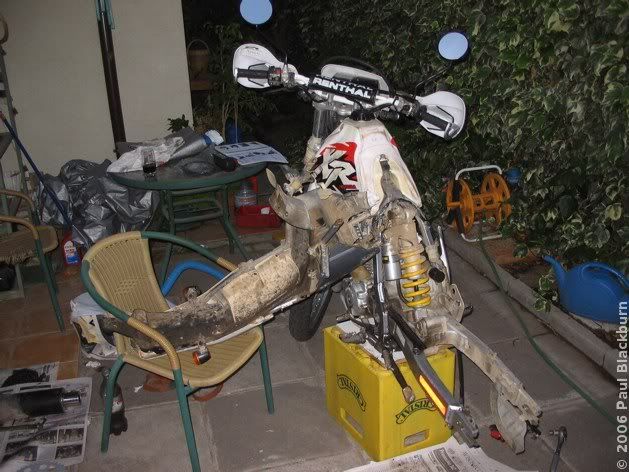
I had no alternative. I rode the bicycle to the mall and bought a 2 x 250 W light stand.
And there was light again!
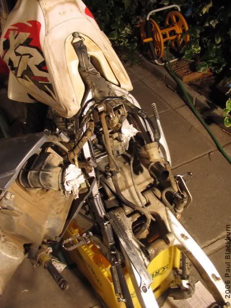
You'll notice a few things in the previous pic. First, the rear sub-frame is still attached to the bike by a bundle of cables. These can't be easily disconnected. Strangely enough, the shop manual states that you just have to disconnect three plugs, and you're done. Not on my bike. I set the tail on a chair, beside the bike. You can also pivot it up on the top subframe bolt, and rest it on the tank, upside-down.
I stuffed the carb and air box holes with paper towel.
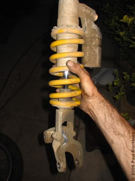
Heres the monoshock and, hanging from it, the shock arm.
I stuffed the carb and air box holes with paper towel.
Heres the monoshock and, hanging from it, the shock arm.
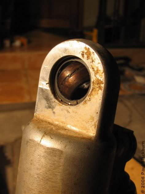
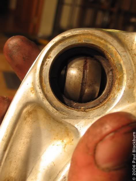
The monoshock's upper and lower sphrical bearings were completely dry. Their design is interesting. They are basically a spherical section, with a groove running around the outer diameter, probably to aid in grease distribution. They allow the monoshock to pivot around its vertical axis slightly.
I cleaned the grease out by hand, using a bit of fresh grease. Throughout this whole maintenance process, I used Versamoly, a lithium grease with added moldybdenum disulfide. This particular pot was manufactured by Versachem.
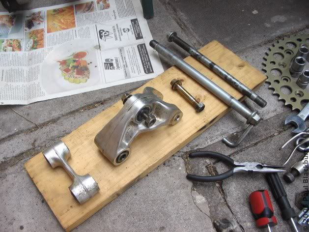
These are some of the parts that I took apart and lubricated. From left to right: the shock link (two needle bearings and their corresponding collars), the shock arm, with two needle bearings and a spherical bearing, one of the monoshock's bolts, the rear wheel's axle, and the swingarm bolt. In the background, the old Renthal rear sprocket, technically brand new, but being swapped out because it was getting eaten away like butter.
These are some of the parts that I took apart and lubricated. From left to right: the shock link (two needle bearings and their corresponding collars), the shock arm, with two needle bearings and a spherical bearing, one of the monoshock's bolts, the rear wheel's axle, and the swingarm bolt. In the background, the old Renthal rear sprocket, technically brand new, but being swapped out because it was getting eaten away like butter.
Below, another spherical bearing, this time from the shock arm. Also completely dry.
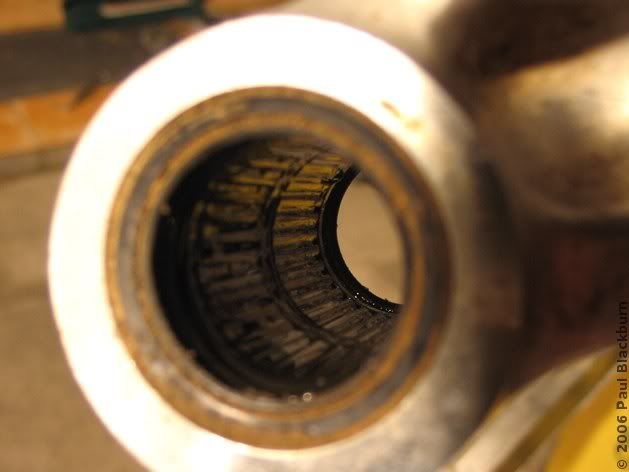
And here are the shock arm's needle bearings. It's strange, but contrary to what I expected, they still had abundant grease in them. I massaged them a bit to get the old stuff out, and then packed fresh grease in by hand.
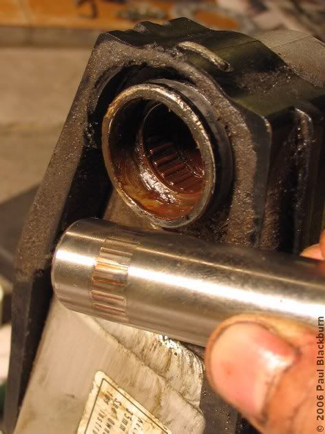
And here's the only damaged piece. It's the left needle bearing's collar. It had enough grease, though it was orange in colour, almost rust-orange. Also, the collar was worn.
That night, I left everything lubed up, and the next morning, put it all back together.
Swapping the Renthal Sprocket for a Generic One
Renthal sprockets may be great in a competition, but aluminium is just too soft for dual-sport use. I wanted to find a 45-tooth steel rear sprocket, and after much searching, was lucky enough to find that the XR 400 uses the same anchor bolts as my bike.
- Renthal rear sprocket (bought because it was the only way I could have 45 teeth on my rear sprocket at the time): nearly 100 bucks.
- Generic brazilian steel rear sprocket: 20 bucks.
AZ Sprockets Chains, HA07.345T, OEM: 41201-KCY-670VAOne last tip: when loosening the rear sprocket bolts with an allen socket, be sure to loosen the lock nut on the other side of the sprocket first. Otherwise, as happened to me, you'll probably bust the allen tool.
Adjusting the Chain Sag
Yawn.
Changing the Clutch Cable
This took me by surprise. I improperly mounted the sheepskin's fastening strap under the clutch cable, instead of over it. This pulled it out of alignment, and made the curved guide tube rub against the cable.
Second Valve Adjustment
I recommend you read the first post about this procedure, if you got here searching for info on adjusting the valves on a 1996 XR 250 R.
First, wash and clean the area around the spark plug, so crud doesn't fall into the engine when we remove it.
I measured the electrode gap, and it was 0.85 mm, right between the 0.8 and 0.9 mm that the service manual states as min and max.
Next, we remove the seat and gas tank, and clean the area underneath.
Here's the bike, ready for a valve adjustment: seat and gas tank off, crankshaft and valve timing covers off.
You can see the adjustment screw, with a slotted head, and the adjustment screw lock nut. These two are attached to a rocker arm.
Rotate the crankshaft until the engine is at Top Dead Center. This will happen when you can see a T through the timing hole. Make sure the piston is on a compression stroke. If it is, the valve rocker arms will have enough play in them (both) to make a slight clicking sound when you wiggle them up and down. If they do not wiggle, you are not on the compression stroke.
It is also important to turn the engine anticlockwise in order to line up the T mark.
Some tips:
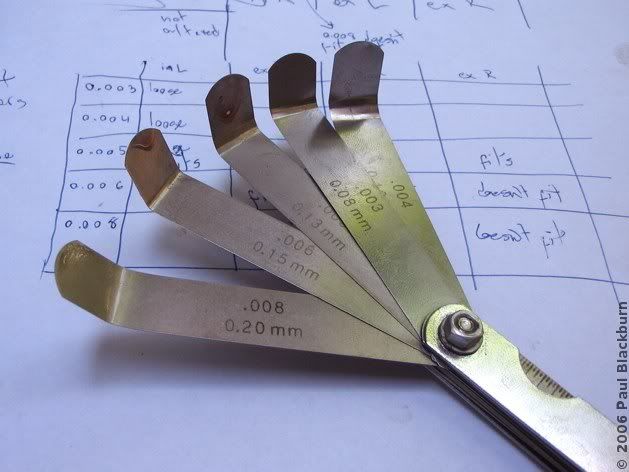
- Remove all feelers that you don't need from the set. Remove the feeler set's metal frame, if it has one. All that just gets in the way. Leave numbers 0.003, 0.004, 0.005, 0.006, 0.008.
- Bend the feeler almost in a right angle 1 cm from the tip. This spares you the fumbling associated with trying to insert a springy piece of metal into the valve gap. Trust me. Just bend them.
- Playing around with the adjustment screw and lock nut can e easy or hard. Sometimes you torque the nut and the screw stays put, sometimes it doesn't. It helps to keep the feeler in the adjustment gap while you tighten the lock nut slightly. Remove the feeler, and give it the full torque. Some people just set the gap to one measure above what is needed, and let the lock nut reduce the gap slightly. See what works for you.
Once the feelers are bent, measuring the correct separation is easy.
At 20641 km, this is the state of the valves, before adjustment.
| Feeler | in L | ex L | in R | ex R |
| 0.003 | - | - | - | - |
| 0.004 | - | - | - | - |
| 0.005 | Fits | - | Fits | Fits |
| 0.006 | Doesn't fit | Fits | Doesn't fit | Doesn't fit |
| 0.008 | - | Doesn't fit | - | - |
The green boxes are the separations specified by the manual.
Regulating the Manual Decompressor System
In the first article on valve adjustments I showed how the manual decompressor works. You must make sure that the manual decompressor does not activate when the front wheel is turned full left or right. Before you cover up the front right hand valve cover, check everything is in order.
Conclusion
The truth is I am in no hurry to do this again. After having finished, I wanted to go for a ride, so I went over to Cuesta Lo Prado, where I found this Chilean Fox.
And what of the bike? Same as always. I didn't expect any changes, and there were none that I could feel. These were just things that had to be done.
Labels: mechanics
posted by durandal at 6:44 PM
![]()


 The Lagoons of the Santuario de la Naturaleza 2: Laguna Los Ángeles
 Race Day At Leyda 4
 El Tabo and the Central Hidroeléctrica El Sauce
 Exploring The Hills Around Lampa
 A Different Route To Baños De Colina
 The Mines of the Cuesta La Dormida
 The Frozen Lagoons of the Santuario de la Naturaleza
 Second Mass Demonstration "For A Fair Tag"
 First Mass Demonstration Against The 'Tag'
 Enduro In Lagunillas
 Embalse El Yeso and Termas Del Plomo
 Ride To Peñuelas
 Cerro Chena
 Race Day at Leyda 3
 Baños de Colina 2
 Carretera Austral: Epilogue
 The Little Giant and Termas del Plomo
 Back on Two Wheels
 2006 Photographic Retrospective
 Race Day At Leyda 2
  Quantum Optics III in Pucón
 Meseta In Chicureo
 Pick Up Your Beer Bottle And Fuck Off
  Planes And Hills
 Cut-Off Road
 Lagunillas
 Laguna Verde 2
 Ride To Anywhere But Aculeo
 Cerro El Roble, Second Attempt
 Baños De Colina
 Some Walk On Water...
 Race Day At Leyda
 Almost Cerro El Roble
 Off To Curacaví with Andrés
 La Serena, Part 3: Back To Santiago
  A Bull, Two Cows and a Chilean Fox
 Escape To Cuesta La Dormida
 Valve Adjustment
 La Serena, Part 2B: Valle Del Elqui
 La Serena, Part 2A: Coquimbo and La Recova
 Mud And Pine Trees
 La Serena, Part 1
 Pimp My Exhaust
 Ride To Laguna Verde
 Ride To La Mina
 Ride To Termas El Plomo
 Camping in Colliguay
 Ride To Portillo
 Ride To Olmué and Con Con
 Siete Tazas
 Watching The Departure Of The Day That Brought Me Here
 Buenos Aires Motorbikes
 Ride to Talca with the Adach Group
 Las Trancas '05
 Towers and Hills
 María Pinto, Melipilla, Aculeo
 Me and my Carb


0 Comments:
Post a Comment
<< Home